The Aquanaut - A new keyboard design from the Sea Collection

Hello keeb lovers,

It has been a long time since I designed a keyboard; the last one, the Manta75 (The Manta75 - A new keyboard design from the Sea Collection - now an opensource project!) date from September 2020, a whooping 4 years !

I did not stand still and made several PCB projects, even one, The Leyden Jar (The Leyden Jar, a tentative PCB replacement for the Brand New Model F Keyboards) that Ellipse is currently using for it’s Model F122 and Beamspring B122.

But keyboard designs ? None…
I needed time, dedication and an idea but had none of the three at the same time … until a few months ago :slight_smile:

Here is The Aquanaut keyboard, a tribute to those fierce divers with their copper/brass/bronze helmets.

As I usually do I’ll only show the keyboard layout for now, more details will come in the future(be patient).

It is a south paw full size, a real full size :stuck_out_tongue:
I plan to make only two, one for work and one for home, they will replace the Winghead boards (The Winghead, a new personal keyboard project) that I still use daily.
The Aquanaut will be my next beater board, a chonker with a no compromise layout optimized for my CAD and programming habits, allowing to easily type numbers while using the mouse at the same time.

See you !

12 Likes

Looking forward to seeing more design pictures :slight_smile:

4 Likes

Me too!

1 Like

Oh my, your Winghead project was amazing to follow along. I can’t believe you’re planning to do it again!

1 Like

Thank all for your warm support!

I’ll try to not disappoint:p

1 Like

4 Likes

Haha !

Here is a bit more information on the project, this time on the PCB design front.

As it is a board for my personal use only I did not bother having several layout options on it: the layout you see in my first post is the one I’ll use and only this one.
This will be a very standard ANSI layout, stepped caps lock only, tsangan bottom row only.
As for the numpad section I do not plan to make any mirrored version (with enter and plus keys on the far left) as I previously used a detached numpad before and found it comfy to use on the left of a board.

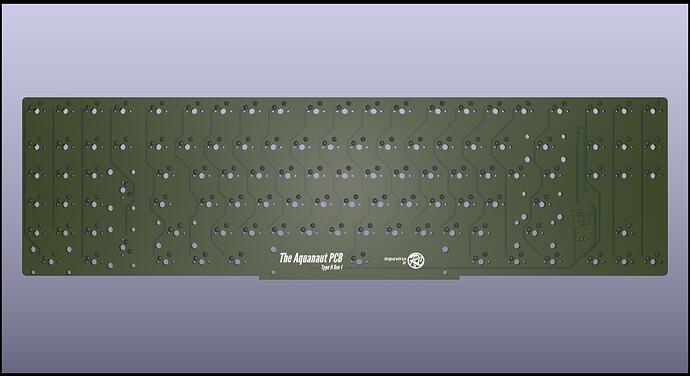
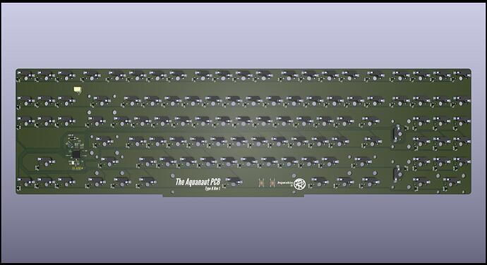
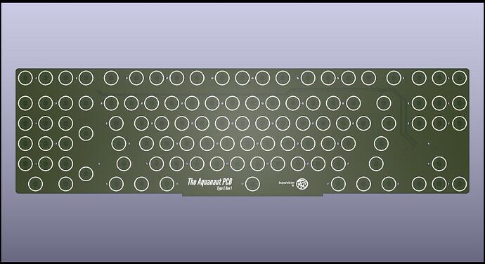
As a direct result the first PCB revision I designed is a ‘Type H’ (hotswap), also in order to easily play with differents switches (I want to try my Cherry MX purple switches and also linears).
I don’t mind soldering at all but desoldering is a bit of a pain in the ass to be honest :stuck_out_tongue:


I used my now familiar RP2040 MCU for the heart.
This is a very basic design with no leds, no nice curved traces and no nice graphics.
It is as simple as it can be to be a reliable keyboard PCB.

Still it is not a lazy design as you may have noticed the strange protrusion at the spacebar location.
The exact same PCB outline will be used in the future for a type C (electro-capacitive, aka Topre like) version. All outlines dimensions are taking into account Topre like component sizes so that everything can fit nicely.
For this capacitive version of the PCB I will most probably not re-invent the wheel and base the design on what did our awsome dude @Cipulot on it’s numerous Topre PCB designs (nearly all open sourced) thank you so much dude to help the community the way you do !

See you!

5 Likes

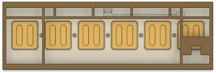
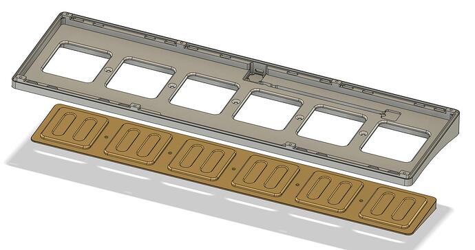
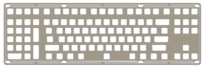
I do plan to give details on the case design very soon but for the time beeing here is some information on the plate design, this also may give you a hint on how everything fits together.

I wanted to keep the same leaf spring design as in the Manta75 so it is totally normal if you find some similarities. I have been forced to add two additional leaves (for a total of six) due to the size of the board. Given the length of the leaf springs this should translate into a moderate to good amount of bounce while not beeing a trampoline.

The area surrounding the leaves and the whole plate is the most unconventional feature for a plate design. This area will be supported by 3mm Orings that will surround the whole top and bottom part of the case.
In short this is a full isolation mount, with Orings all around that visually makes the feeling that there is a full hermetic sealing, reminding the kind of sealing you can see in divers helmets.

1 Like

Time to give some details on the case itself !

You’ll see that the design is very classic and simple and a completely different vibe than the Winghead and Manta75.
Reason of the simplicity is that I am not a professional designer and don’t want to risk overdoing things and obtain something ugly to look at; I am just a NERD that like to hack and make things when at home.
Another benefit of selecting a simple design is that all shapes and dimentions are all well defined (it is difficult to specify organic curves in a technical drawing) and this reduces misunterstanding issues with the CNC provider.

And of course I took a lot of inspications of existing keyboards.
To summarize the inspiration and the general look, the Aquanaut is a mix of a Geon’s F1-8X 722 and a Smith & Rune Iron 165 with a tad of OTD Koala vibes :stuck_out_tongue:

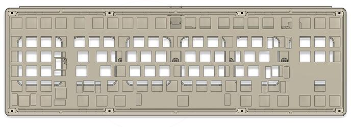
Here it is from the top:

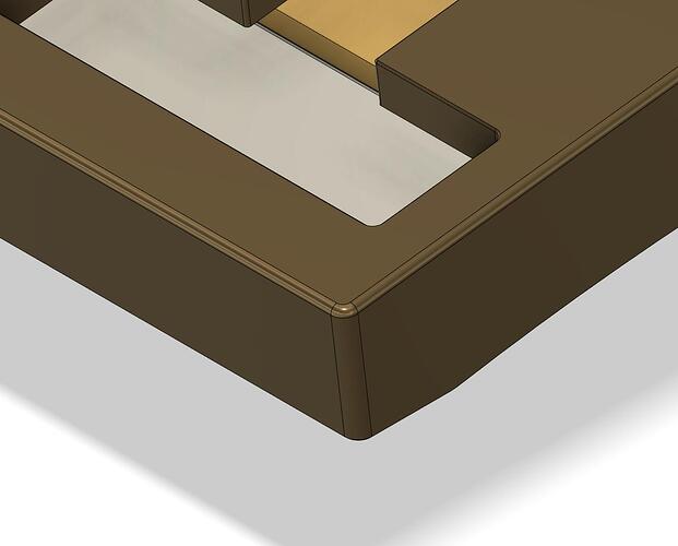
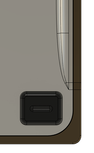
This is a very boxy look with corner radiuses of only 2mm and top fillet of 1mm, just what is needed to still have something comfy to the touch but not more.
As for the top and side bezels, those are bigger than usually found in Korean standards (that are 0.5u top/botton and 0.25 on the sides) but are kept to a minimum size given the mounting system used.

Here is a closeup for better view of corner radius and fillet:

As for the back:

This is where you can see the most Iron 165(and 180) inspirations. I always loved the back of those old Smith & Rune keyboards and their boxy look.

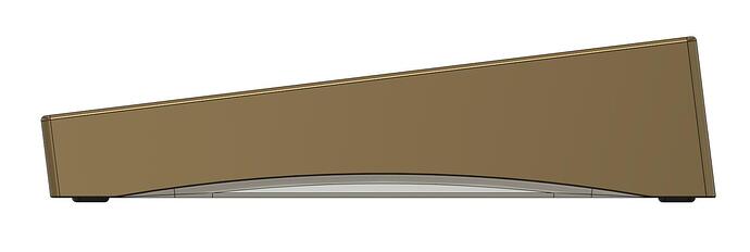
And now the side:

A small OTD Koala curve (it is an arc circle with a well defined radius) of 5mm tall and 5 mm deep, just what is needed to be able to grab the board easily.

You can see here that the Koala feature is done very closely to what was done on the old OTD board, just adding a bit of curves on it to not cut my fingers when grabbing the board. It is also less deep than in original Koala design (at around 2cm) to take into account the bottom internals.
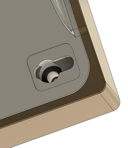
And you also have a closeup of one of the 8 feets, those are original Geon F1-8X feets to have a ‘screwless’ design.

They nicely hide the 8 screws used for assembly.

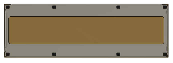
As for the bottom:

You can see the 8 feets, the big brass (or maybe copper ?) weight and the small Koala features.
The weight traverses the whole bottom part like seen in the previous pictures. I once considered to make the whole bottom piece full brass but the board would have weighted more than 6KG ! Totally absurd, so no :stuck_out_tongue:

Here is a better view of the bottom and weight assembly:

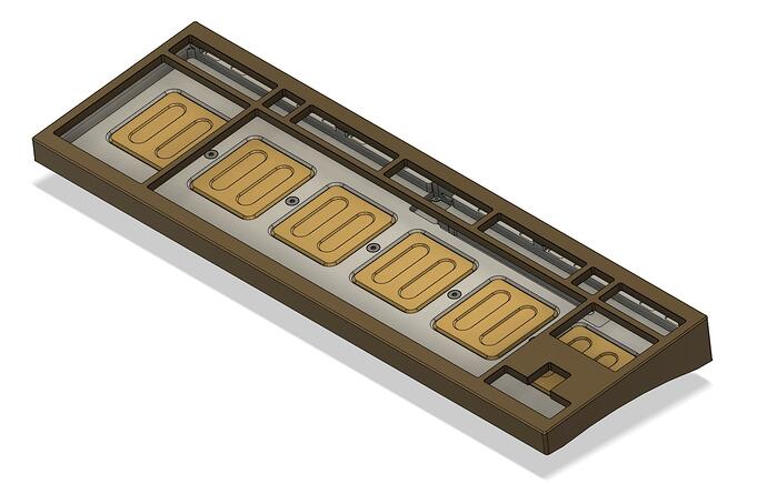
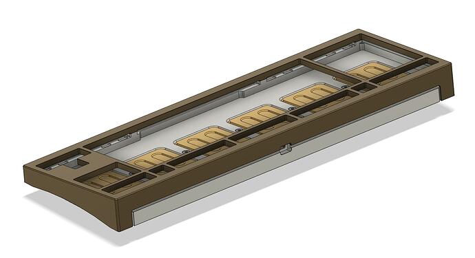
The plate and bottom assembly is like this:

This may explain a bit more why the shape of the plate.

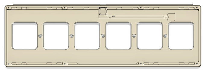
And without the plate:

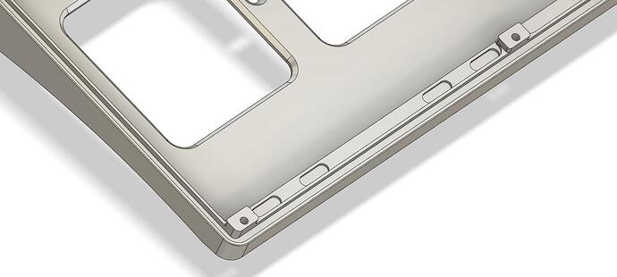
And a perspective closeup:

You can better see where the 3mm Oring will fit all around the bottom and after the screw poles(the same feature is present on the top part). Just like the F1-8X Viton Orings will be used.

There are 4 small rounded rectangle shaped cutouts for each leaf spring to optionnally put 3mm gaskets in them, this to tune the bounce depending on taste and plate material. There are none under the spacebar as there are no space for them to accomodate Topre spacebar stabilizer parts and to have a tad more bounce in this area.

And a few perspective views to finish:

Some numbers:

The estimated weight for top + bottom + weight is around 3.8KB, it is a heavy boi but not absurdly heavy considering the size.
The lip front height is around 17.8 mm and the adjusted front height is 19mm. The feets adds 1mm. The typing angle is 7 degree. Those combined should make a comfortable typing experience.

Work to be done:

I still need to double/triple check that dimensions are correct and that no features are missing.
Also have to decide the CNC manufacturer and the finishes I’ll want.
This will take me quite some time …

8 Likes

Man I love all the things I just saw and that you described :slight_smile: When can I get one (jk, unless?)

1 Like

Unfortunately, I will be probably just for me :frowning:
I will pay a good amount of money for the two boards that will be very expensive and potentially flawed prototypes.
I’d say that there are a lot of safe options out there. Would you like to pay a lot and take this amount of risk ?

I may open source it in the future though.

1 Like

Yea I remember you mentioning it’s just for yourself, but if you ever figure out how to make a duplication raygun. Let me know lol

1 Like

Haha!

Ok :wink:

Hi there !

Told you that I was planning to make an EC version of the PCB ?
Here it is, recently designed :stuck_out_tongue:

In order to minimize risks or design errors and gain time I took @Cipulot footprint ressources and inspiration from numerous designs he already made available on Github.

Although Cip made 2 layers designs in the past I took no risks and made a 4 layers designs like it’s EC60 PCB.

It may look more complicated to design a 4 layers board but it is in fact much easier, specially for an EC PCB design where signal integrity is key to a good and reliable key press detection.

You can see the gigantic amount of mouting holes, each marked with an arrow.

Here is a closeup view of the PCB.

You can see that they are traces on all 4 layers of the PCB, doing this on a 2 layers PCB would have been a nightmare for me to do.
To preserve signal integrity and have a solid ground plane on all the layers you can see vias at all crossing traces.
And one particular (blue) trace even has close vias on all it’s length, in order to have extremely good noise immunity on it. This trace carries the signal of the EC voltage response of an EC pad, a very fast transient signal and with quite a low amplitute (in the hundreds of millivolts).

For the EC version of the Aquanaut I plan to make a stainless steel plate.

See you !

7 Likes

I did the plate design for the EC PCB soon after.

As the plate will be in stainless steel, much stiffer than aluminum or FR4, the leaves are thinner to compensate somehow; they go from 3mm to 2mm thickness.
I do not expect significant amount of bounce from the leaves here, just a tiny bit to not have an overly stiff plate. Also the EC domes should dampen vibration significantly and the typing experience should be enjoyable as a result.

There are 1.6mm holes at the same positions as on the PCB, they will be tapped to accomodate standard M2 screws. This will follow the common method used on EC boards with metal plates, no spacers and the use M2 screws that goes in between switch housings.

LaserBoost is now able to tap holes, I will most probably use their services for the plate manufacturing.

4 Likes

Your RP2040 MCU-based keyboard PCB design sounds practical and forward-thinking. The simplicity of the current design for reliability is a great approach. The planned Type C electro-capacitive version with the same outline considering Topre-like component sizes is an exciting prospect. And basing the capacitive design on the work of @Cipulot is a smart move. Looking forward to seeing the final results. Best of luck with your project!

1 Like

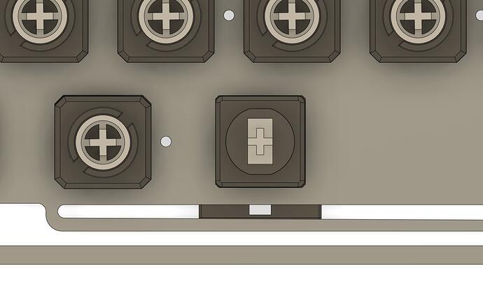
I messed a bit with testing EC PCB + switches + plate assembly in Fusion360.

This kind of process is extremely important to detect potential fitment problems that could happen due to a mistake in the design stage. It much better to lose time fixing things in the design than losing money manufacturing flawed parts.

And you will shortly see how important it is.

Here is a global image of the EC assembly.

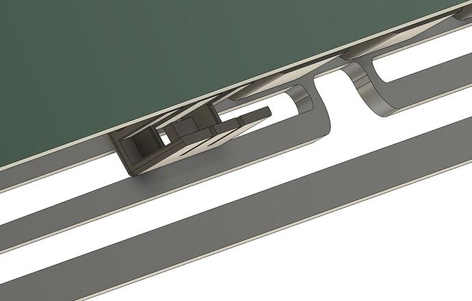
It looks normal in appearence, but lets have a look closer at the spacebar stabilizer location.

Damnit !
The stabilizer housing collide with the leaf :frowning:

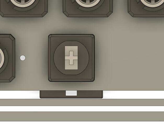
To the design again to fix this issue, just moving the leaves back 0.5mm is more than enough to give clearance.

The good news is that holes placement in the plate and PCB are perfectly aligned :slight_smile:

I should really check for keycaps fitting now to be 100% sure that everything is correct …

5 Likes

This is the same problem that few MX cases-later-turned-EC also have - the spacebar stab has to be installed 180 degree rotated, making the wire go up top, if you get what I mean. Then that introduce another issue where the wire is conflicting with the 1u housings of the bottom row, thus people resorting to cutting away the bottom wall of the impacted housings (7-8 pieces).

Thus it’s really great to see you’re designing MX & EC at the the same time like this.

IMO this should be the motto to every designers out there

2 Likes

This is really good, looking forward to learn more about it.

1 Like