Hello keeb lovers,
It looks to be of interest to several people in this hobby to revive their older custom boards, often staying in their box or taking dust because of no more working of unstable PCBs.
And it looks to be true for the very beautiful M65-A keyboard made by RAMA, plagued with PCB issues, see in the link below:
M65-A Replacement PCB
So I decided to do something to remediate that and ‘The Phoenix Project’ was born.
We are talking about the M65-A replacement PCB, and it the first (No 1) of maybe future efforts to make those old nice customs clack again.
As it was not clear if a hotswap or solder PCB would be preferred I have designed both:
- Hot swap: The Phoenix Project No 1 - Type H
- Solder: The Phoenix Project No 1 - Type S
Those two versions have a lot in common:
- Both are electrically compatible and should share the same QMK/VIA/VIAL firmware.
- RP2040 MCU with 2MB flash memory.
- Underglow RGB.
- ESD protection for USB VBUS and data lines.
- EMI protection with a ferrite bead.
- Overcurrent protection with a resettable fuse.
- No key lighting (uniform lighting is present on the original PCB).
- Good old USB mini connector like on the original PCB.
- Reset and Bootsel buttons.
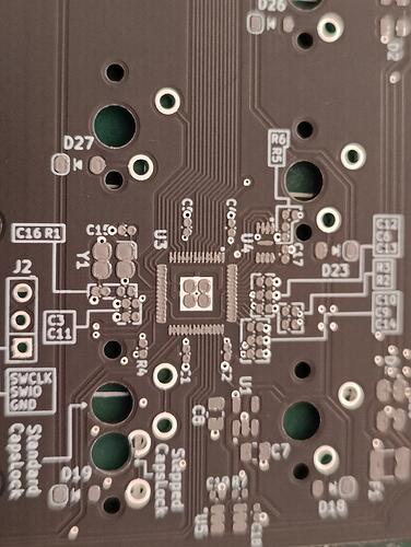
- Header for SWD debugging.
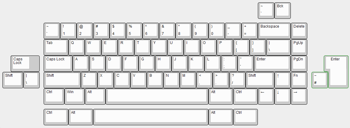
As for the selected layouts, only one is available for the Type H:
- Full backspace
- Stepped Caps Lock
- Winkeyless Tsangan bottom row (7u spacebar and 1.5u mods)
A you see this is not a normie layout like you can usually have on a hotswap board, this layout may potentially please to people that often look at a solder PCB to have this kind of layout.
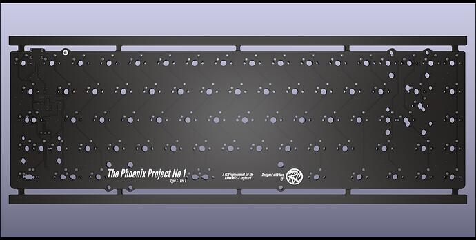
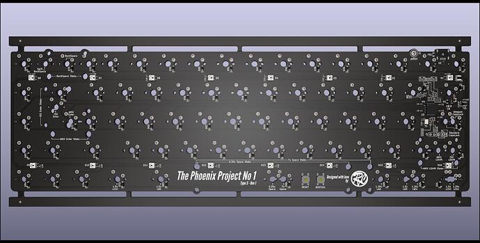
The Type S has a more extensive layout, including ISO, without going crazing in order not to have a PCB Swiss Cheese.
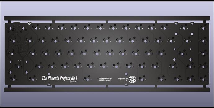
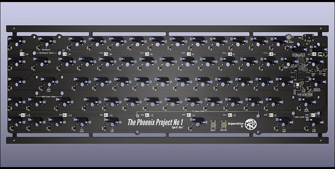
Here are some Kicad renders for the Type H:
And for the Type S:
Did you see the protruding hole near the USB port ?
This is to solder a wire attached to a connector that will be later screwed to the case.
I did that because specially on Nylon bottom versions of the board a lot of static can be generated and this could ESD zap several components on the PCB. This will allow to have the case properly grounded and hopefully make the PCB much more ESD safe.
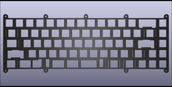
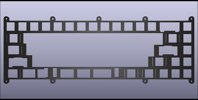
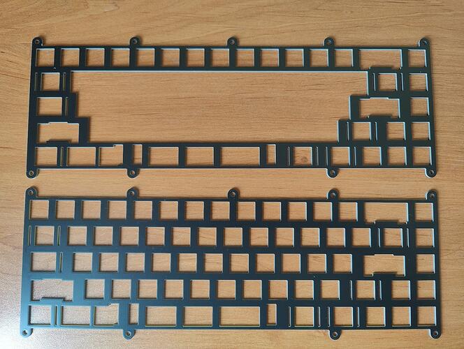
Also designed several plate options, half plate and full plate, but you could still use the plate that came with your board.
If you look carefully not all screw holes are used on those plates, and specially under the space bar.
This is done in the hope to have a bit less stiff typing experience compared to the original plates.
Also there are cutouts under the spacebar in order to thin out the sound of this key a bit.
Most obvious formats will be .DXF and .STEP so that anyone could make their own in the future.
Also have a PCB version of the plates as you can see below in the Kicad renders.
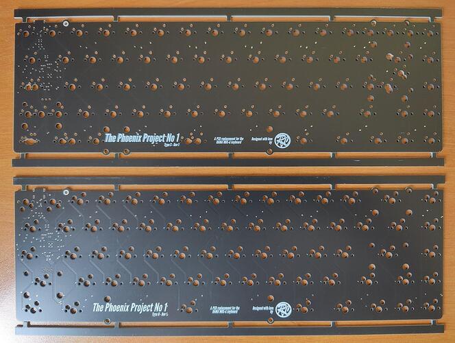
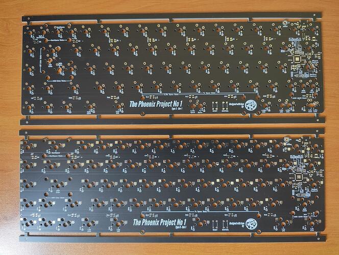
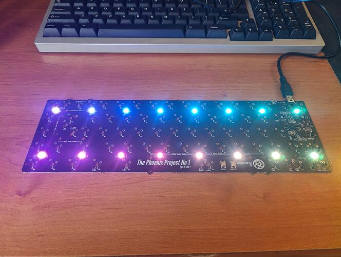
The status of the project is not yet complete, but already ordered 5 units of each PCB and plate versions, all with black solder mask.
Need to assemble them by hand before conducting tests to check that I’ve done everything well.
When the project will be in a shape that I think is good enough, I will open source it with a permissive licence so that anyone will be able to manufacture it without asking anything, even vendors.
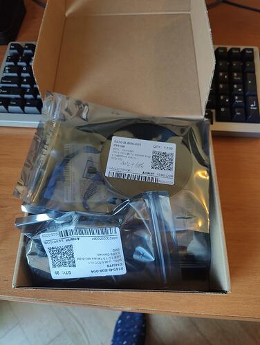
Time has been taken so that even individuals can order their own assembled PCBs at JLCPCB, all components used are available on their website, the only thing is some components can be out of stock sometimes (this is the case now for the RP2040 MCU and the Kailh hot swap sockets).
I’d like to thank our good buddy @pixelpusher for all the great information and feedback he gave me during the designing process, thank you so much dude !

