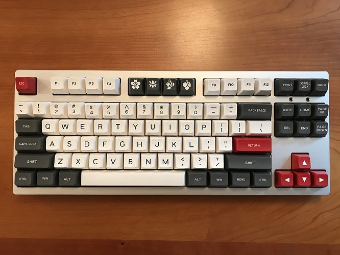
Build #6: Phantom TKL
With five builds complete, and a few more essentially complete except for final decorative touches, I thought it was time to attempt something a bit more challenging, as well as put together what I’ve learned up to this point. Some goals going into the next project:
- I’ve done a bunch of 60% builds and one ortho, so it seemed like time to try a larger board.
- All of the PCBs I’ve used have had at least some of the components pre-soldered. How about a bare PCB?
- Stabilizers remain a sore spot in my builds, particularly with respect to upstroke noise. It’s time to bring out bigger guns.
- I’ve been avoiding getting into QMK, for no particularly good reason. Time to correct that.
- Continue exploring Sorbothane treatments for sound dampening.
- More switch lubing practice. (Wait, I hear you saying, you didn’t tell us about any switch lubing before! That’s true. I write up builds only when they are done - I felt that would be clearer than trying to follow a rolling narrative of all of the simultaneous projects going on. You’ll hear about my conversion to the world of switch lubing in later build logs, even though that experience actually happened prior to this build.)
Putting all of that together, I decided to attempt a Phantom TKL build. If my understanding is correct, this is a comparatively old PCB, with origins in a 2012 group buy and a lot of community activity on Phantom builds during that same year, but as of this writing, cases, plates and PCBs remain readily available. That could be good or bad, but since an evening of googling didn’t reveal any obvious non-starters for a Phantom, and there were good online resources documenting gotchas, I decided to go for it.
Switch prep
Back before I did my first build, I played with a bunch of switches in a switch tester, where I discovered that I’m a tactile switch guy, and of the switches I had available, Zealios were my fave. However, there were a couple of other switches that felt good on the tester. The MOD-L tactile has a 45g actuation force, which is also roughly the actuation force on a 62g Zealio (recall that Zealios are advertised by bottom-out weighting).
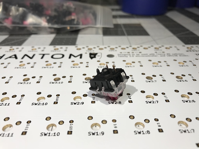
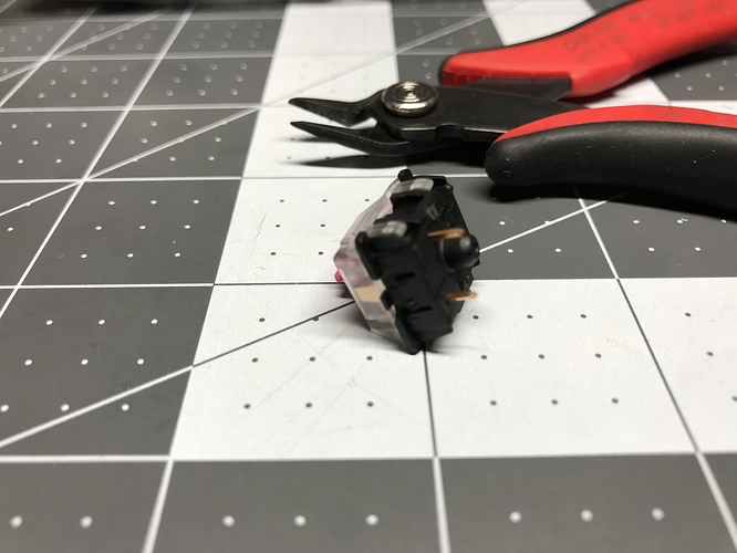
Because the Phantom PCB doesn’t have the holes for the plastic side pins on the MOD-Ls, the first step was to cut those pins off.
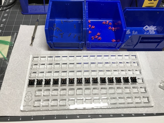
After that, on to switch lubing. 87 MOD-L Tactile switches, meet Tribosys 3204. I like to take my time with lubing, to make sure I’m applying the desired amount of lube in the intended places, but it still takes me longer than I feel it should. I would estimate around four minutes per switch on average, including disassembly, lubing, and reassembly. Midway through the lubing effort, I acquired an acrylic switch lubing plate to organize the lubing process.
I’d consider one of these switch lubing stations a worthwhile investment if you plan on doing more than one or two boards’ worth of lubing; being able to lube in an assembly line made the process more efficient. I can’t say that it made the process radically more efficient, though. I suppose practice makes perfect.
Stabilizer prep
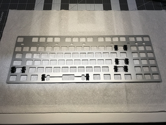
This was my first time working with plate-mount stabilizers, and after a bit of fiddling to figure out how they actually mounted on the plate, ultimately they’re not that different in function or form from PCB-mount stabilizers, so disassembling, lubing, and reassembling goes pretty much the same way as it does for PCB-mount stabs. Up to this point, my standard stabilizer treatment has included clipping, lubing with SuperLube, and doing a “band-aid” mod with silicone pads instead of bandaids, and I could have just done those mods and stopped there.
However, I’ve had problems with upstroke stabilizer noise in other builds, and I wanted to directly address that issue in this build. @Walkerstop’s silencing mods - clipping all four slider stems and strategically inserting O-rings into the housings - looked like a novel and interesting approach to the issue. I have little to add to his video illustrating the mods (see the resources section at the end of this build log), other than encouraging you to have a good pair of tweezers on hand if you attempt it. And perhaps a magnifying lens if your eyes are bad like mine; those O-rings, and the space in which they fit, are tiny.
PCB prep
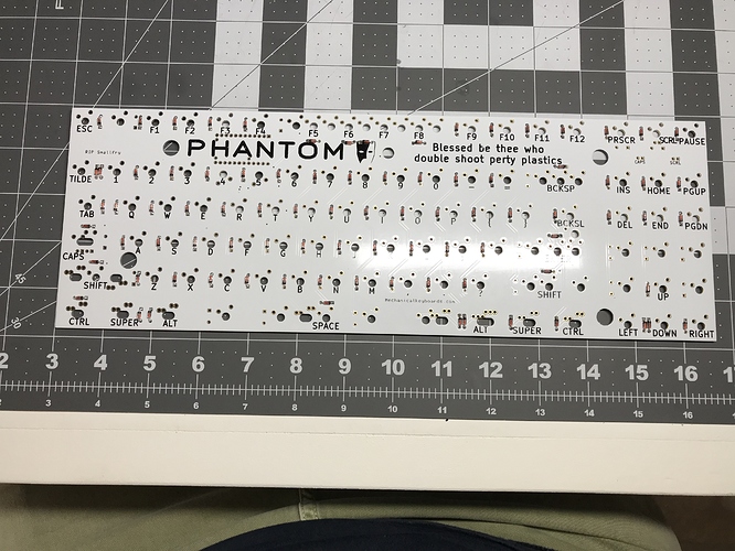
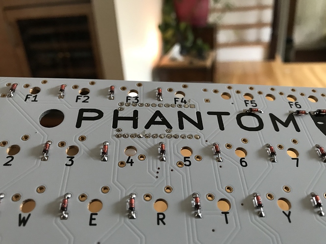
The Phantom PCB does not have pre-soldered diodes, so that’s the first step. We need one diode for each key we want to enable. Before I saw the PCB, I was worried that identifying the holes for the diodes would be difficult, but I needn’t have worried; the diode holes were marked with the same SW<num>:<num> label as the switch holes. So, the only remaining issue with diodes is to be sure they’re soldered in the right direction. Each diode has a black band on one end - that end needs to go through the square diode hole on the Phantom, and the other end through the round hole. Once this was done, I used an old crappy multimeter with a diode testing mode to verify the correct orientation for each diode. Note that switches SW4:3 and SW4:4 are upside down, so you’ll have to switch the multimeter probes for these two switches.
Because I’m me, I added diodes to the five “extra” keys the Phantom offers, between the arrow cluster and the
2x3 insert cluster. I thought enabling these keys might be an interesting test case for my first foray into QMK.
Note that the photo above shows the PCB before those last five diodes were soldered into place.
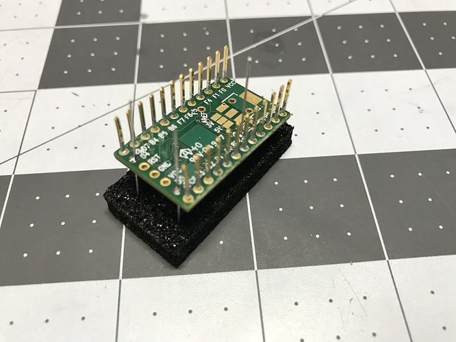
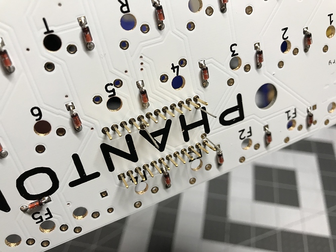
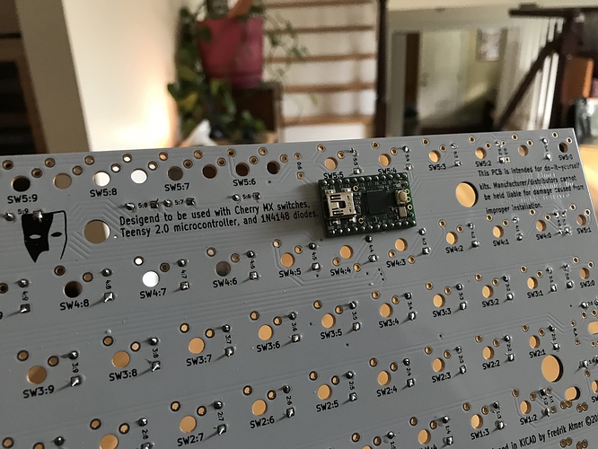
Next up: soldering the Teensy board to the Phantom PCB. Before doing anything else, I plugged the Teensy into the PC to verify that a light on the Teensy was blinking on and off for a 1 second cycle, indicating that the board is functional. Next, I had to remove the spacers from the Teensy board. I ended up doing that with a very small flathead screwdriver to gently pry the spacers away from the board, using the screwdriver at several different locations on the spacer to distribute the force evenly. Next, I had to solder pins onto the Teensy board at locations D4, D5, and E6, and as recommended, leads clipped from diodes serve adequately as pins for the Teensy. Soldering these pins onto the Teensy would be a three-handed job, unless you still have the protective foam that came with the Teensy, in which case you can seat the Teensy and the pins in the foam to hold everything stable while you solder the pins. This worked well. It’s worth seating the Teensy on the board at this point, to be sure all of the pins are going through the holes.
Now, before soldering, with the Teensy seated, you need to clip all of the pins so that they are flush with the Phantom PCB surface, so that you can get the solder joints as flat as possible. This is necessary because the switches for four keys are seated in close proximity to the Teensy, and if these solder joints are not flush with the board, they have the potential to push the switches for those four keys out of alignment. Flush cutters are essential for this task.
With all of the Teensy pins flush cut, it remained to solder the Teensy onto the Phantom PCB. My solder joints weren’t perfectly flat, but a quick switch mounting test looked OK, so I decided to proceed.
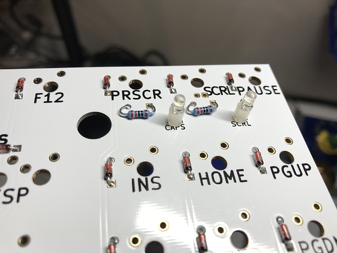
Finally, the last step for PCB prep involved soldering resistors and LEDs for the Caps Lock and Scroll Lock keys. The case for this build was a Filco-style case, with light cutouts below the scroll lock key. The LEDs I had were rated at 3V 20mA, so (5V-3V)/20mA implied a 100-ohm resistor rating, but they were also high-brightness LEDs. I was worried that at max current, this type of LED would be far too bright for use as indicator lights. To guard against that, I used a couple of 220-ohm resistors. Aside from that, the only other issue is that the LEDs needed to be mounted on spacers, but that’s not a big deal.
After soldering, a quick tweezer test confirmed that the indicator lights were working, albeit still quite bright.
QMK
The QMK documentation is pretty reasonable, and I didn’t run into any trouble installing MSYS2 on Windows or using git to get the latest QMK code. Remember those extra five diodes I added to the PCB? Those additions meant I had to create a new layout (description of the physical key layout) for this 92-key Phantom, but that turned out to only involve editing a couple of files (these changes are now in the qmk_firmware repo on GitHub). After doing that, the process of compiling a default keymap is just a matter of running the util/new_keymap script, using make to build the firmware, and then flashing the resulting hex file to the Teensy with QMK Toolbox.
It took me a while to work through all of this the first time, but there weren’t really any problems. It was quite satisfying to flash the Teensy, fire up a keyboard tester, grab a pair of tweezers to test switch points, and find that I had a fully functional PCB and controller. Sweetness!
I’m in the process of going deeper with QMK, and I’m working on a unified keymap for all of my boards using the userspace support - but we’ll save that discussion for another time. In retrospect, I should have started poking around QMK much sooner. There is a lot of great stuff there, and it’s worth looking at all of the keymaps and features other people have contributed.
PCB/plate dampening
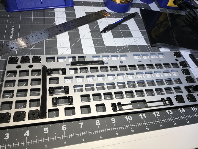
Bring out your Sorbothane! Having tried 0.25" thick sheets as part of a PCB/Sorbo/plate sandwich, and finding that just too thick, I gave it another go with a 0.188" sheet, cutting in into 1/4" or 1/8" wide strips and laying these pieces on the wider parts of the bottom of the plate.
Unfortunately, this was also too thick; I wasn’t comfortable with the pressure that was going to be necessary to get the sandwich soldered together. My janky solution was to use scissors to shave roughly a fifth of each strip away. This was anything but a precision job, but close enough to get some strips that were making contact with both the PCB and the plate in a more gentle fashion.
This really made a difference - before the Sorbo sandwich, I could hold the plate/PCB assembly and get noticeable plate ping by just tapping the plate with my knuckle. Afterwards, a nice dull bass thunk.
Switch mounting and soldering
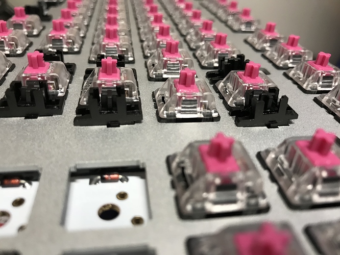
Not much to say here - for better or worse, this part of a build is becoming relatively routine.
It was around here, nearing the end of the build (or so I thought at the time), that I realized I’m an idiot. The 92 key firmware and plate support is interesting, but it would be a lot more interesting if the case top actually supported it. Sigh. I guess I have an excuse to go see about machining aluminum now. In the meantime, at least we all know those PHANTOM keys (ha, see what I did there) would work.
Final assembly: case dampening and a custom USB port
This ended up being the longest part of the entire build, due to my dissatisfaction with the way the Phantom was going to connect to a computer. You may have noticed from earlier photographs that the Teensy has a mini USB port, aimed horizontally across the PCB. The Tex TKL case has an opening where a port would go, but there is no mounting of any kind to hold a USB plug or connector housing - so, you’re meant to plug a USB cable into the Teensy and screw the case together with a cable dangling out of the hole in the back of the case. Having a cable dangling out of an open hole triggers my OCD - I want a female port there, like every other keyboard I’ve built so far.
So what can be done about it? I thought I would get a short male-to-female USB extension, say 6", plug the male end into the Teensy, and then see how to make the female end of the cable fit nicely into the case opening. I didn’t have a clear idea exactly how I was going to make it “fit nicely”, but I assumed some idea would present itself once the cable arrived and I could directly evaluate cable mounting and placement.
The first problem was apparent immediately. The hard plastic housing for the female end of the cable was too big to allow for clean positioning in the case opening, so I had to spend some time gently filing down the plastic until I had created a “shelf” on the housing, allowing the housing to fit flush with the case opening. This was trial-and-error with a needle file, and it took a while to get enough material filed off of the cable housing. Even then, I still hadn’t solved how to mount the filed housing into a stable position.
It was at this point that the next two problems presented themselves. First, plugging the male end of the cable into the Teensy and trying to manually align the PCB with the case revealed that the the male end of the cable was just a bit too thick for the PCB to sit cleanly atop the case bottom. Back to the needle file. Second, and more problematic: the 6" cable was just too long to fit comfortably in the narrow recessed area in the back of the case between the Teensy and the case opening once the PCB/plate was put in place. Sigh. Time to level up to cable splicing.
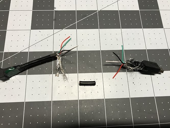
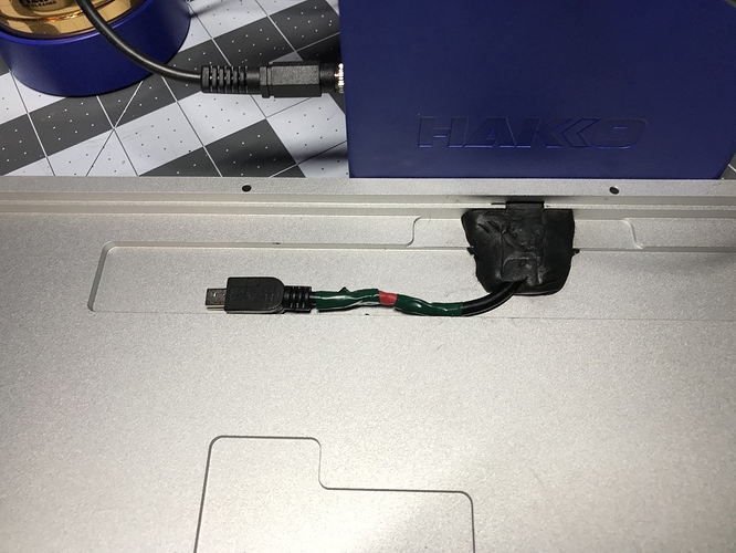
Fortunately, there are any number of guides on splicing USB cables. I was able to cut out a couple of inches of excess cable, strip the outer casing and the ends of the four wires inside the cables, put heat shrink tubing around each of the four wire ends and one larger one around the whole wire, splice the internal wires (color coded, thankfully), solder them together, slide shrink tubing into place over the solder joints, and use a heat gun to shrink the tubing into place. I mismeasured the length of the outer shrink tubing, so I ended up using a bit of electrical tape on either side of the outer shrink tubing to make sure no wire was exposed. Definitely not the prettiest work I’ve ever done, but I ended up with a working ~4" USB extension, which fit just about right in the available space.
Now - how to provide a more permanent fixture for that pesky female USB port in the case opening? I eventually ran across a suggestion to use Sugru for fashioning housings, and after looking at the details, decided to give it a go. When a packet of Sugru is opened, you’ll find a small knob of moldable putty, which you can shape to your heart’s desire, as long as your heart’s desire can be realized in 30 minutes - the time you have available to shape it into the desired form before it begins a 24-hour curing process.
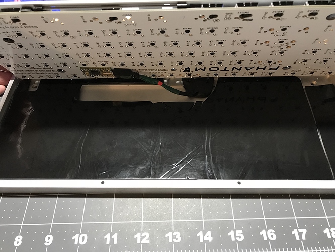
I positioned the female end of the USB cable in the case, and after kneading the Sugru, I manually fashioned a housing, making sure that it made good contact with the case, and making equally sure that it left a bit of vertical clearance for the PCB. 24 hours later, I had a hard silicone miniUSB housing, and, if not exactly a work of sculptural beauty (OK, it’s an ugly knob), at least it’s acceptably solid and stable. Phew.
For the base of the case, to get more sound dampening, I cut a sheet of 0.1" Sorbothane, with cutouts for the Teensy, the cable, and the Sugru plug.
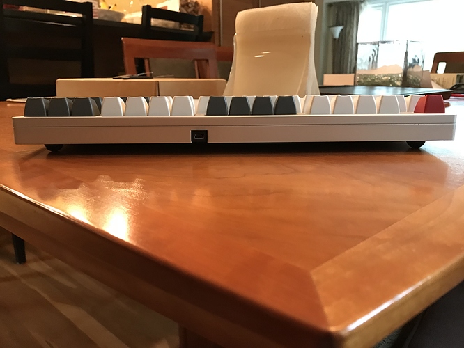
From here, the rest was routine - screw the two halves of the case together and put in keycaps. I’ve got a keyboard! And I can flash new stuff to it! (Note: since the Teensy is now buried inside the case, you won’t be able to get to the reset button to put it in bootloader mode. Shift-shift-pause is the droid you’re looking for.) The Sugru mold turned out OK, too.
And, as a final bonus, the Phantom’s weight is mildly intimidating. Who doesn’t want intimidating heft in their lives? Not this guy.
Lessons learned
- Sorbothane thickness matters for plate/PCB application. It’s going to be really nice when this parameter is dialed in; even the hack job treatment I applied was still a noticeable sound improvement.
- Sorbothane is a comparatively expensive case dampening option, but every time I’ve used it, the result is really pleasant, both in sound elimination and added heft.
- Keep the foam that ICs like the Teensy are shipped in - it’s reusable as a poor man’s mount if you need to do some detailed soldering work and a spare set of hands aren’t available to help out.
- @Walkerstop is on to something with his stab mods - the fully clipped sliders and O-ring mods are working very well for me on this board. Almost no upstroke noise from any of the stabilized keys, and in fact it really is less upstroke noise than on the unstabilized keys. If this works for PCB-mount stabs, and I don’t know why it wouldn’t, then this is likely to become my standard approach going forward.
- Lubed MOD-L Tactiles are nice enough, but the stems are more wobbly than those on Zealios, which I still prefer.
- The barrier to entry for QMK work is not nearly as daunting as it originally seemed, thanks to good project documentation. I’m looking forward to more firmware hacking.
- Remember those four keys right around the Teensy? The 4 and 5 keys are two of those keys, and what I first thought was stem wobble now looks more like I didn’t get some of the Teensy solder joints as flush as I thought I did - the keys are tilted slightly forward. The MOD-L stem wobble disguised this to some extent, but I suspect I’ll have to go back in and improve those joints.
- Short cable splices require some care. It’s tough to get the right amount of wire stripped off of the ends of the cut cable, and you want the heat shrink tubing to be long enough to cover your splices, but far enough away from the soldering iron that you don’t prematurely shrink the tubing. I erred too far towards the former problem.
- Sugru works for fashioning plugs, and so far, the plug seems to be stable when I remove and insert the USB cable. If I were to do it again, I’d spend a bit more time using a straightedge to square off the shape, and even then, if you want the inside of your builds to look as presentable as the outside, this mod is likely not for you.
- Wear gloves when working with Sugru - it stains the hands, and removing the residue is somewhat difficult. The only suggestion which worked for me at all - rub the stained areas with dry toilet paper(!?). Wasn’t perfect, but was noticeably better than various cleaning agents.
Build resources
I found the following resources helpful for this build (and others), and this build log seems like as good a place as any to give credit where credit is due, when I was able to determine who put up the resource. Also, if one of the unattributed things is yours and I missed you, let me know and I’ll fix it. You deserve the props.
- Phantom instruction guide
- Reference photos from another individual’s Phantom build
- Phantom hardware mods
- Sugru discussions here and here
- Sorbothane discussions here and here
- Switch lubing guides: here (thanks @Krelbit) and here (thanks @Quakemz)
- Stabilizer mod guides: here (thanks @TaehaTypes) and here (thanks @Quakemz) and here (thanks @Walkerstop)
- Splicing USB cables
- QMK setup
- Firmware flashing with QMK Toolbox
Specifications
case: Tex TKL aluminum (silver)
case mods: spliced USB extension with filed plugs and Sugru fixture
case dampening: sheet of 0.1" 40 Duro Sorbothane, with cutouts for USB cable and Teensy
PCB: Phantom Dual Layer TKL w/ Teensy 2.0 controller
plate: Phantom TKL Anodized Aluminum (silver)
LEDs: Filco-style caps lock & scroll lock: 3mm T1 white (3V, 20mA) w/ 220-ohm resistors
switches: MOD-L Tactile
switch lubing: Tribosys 3204
layout: TKL ANSI (+ the "Phantom 5")
keycaps: SA Foundation (Maxkey)
stabilizer: Cherry plate mount
stabilizer mods: clipped (all four legs); lubed housing, sliders, & wire ends with SuperLube; bandaid-style mod with silicone pads; O-ring upstroke silencing
plate/PCB dampening: 1/4" and 1/8" strips of 0.188" 30 Duro Sorbothane shaved to approx 0.15" thickness
HxWxD (without feet or caps): 0.88" x 14.13" x 5.56"
HxWxD (without caps): 1.25" x 14.13" x 5.56"
HxWxD: 1.75" x 14.13" x 5.56"
assembled weight: 3.69 lbs
